Project Description
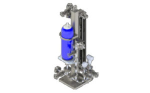
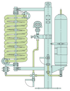
CGT 64C – CLOSED LOOP SYSTEMS
- Design construction available with
finned tube, water or air coolers with fan - Barrier pressure is created without any
need for connection to a nitrogen
supply - Modular design combination available
with a wide variety of system
components and instruments selection
possible - Pressurisation is achieved through a
pre-loaded bladder accumulator - Nitrogen cannot get into the barrier
medium or process medium, because it
is separated from the barrier medium by
membranes in the accumulator
- The BFS is designed to perform the following
functions of a barrier system: - To pressurize the barrier chamber
- Leakage compensation
- To cool the seal
- Pressurization (> process pressure) prevents the
process medium from getting into the barrier circuit or
the atmosphere. Pressurization is supplied by a
pressure accumulator which is pre-loaded with
nitrogen. Circulation in the barrier circuit takes place by
the thermosiphon principle or by forced circulation, e.g.
with a pumping screw.
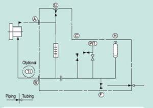
- Operating and installation diagram for a CGT 64C.
- A. From mechanical seal
- B. To mechanical seal
- C. Fill
- F. Drain
- G. Vent
- H. N2 Precharge
- Chemical industry
- Oil and gas industry
- Petrochemical industry
- Refining technology
- PED 2014/68/EU (Design and production in
accordance with EU Pressure Equipment Directive) - ASME VIII, Div. 1 (Design, calculation and production)
- Circulation in accordance with API 682 / ISO
21049: Plan 53B - Pressurised barrier system (closed circuit) is
employed for applications in sealing systems
with operating parameters of high pressures
and/or for hazardous/environmentally
harmful processes. The BFS (Plan 53B)
range is available with a pressure
accumulator, cooler (finned tube or water or
air cooler with fan) with a wide range of
instruments.


