Project Description
- Accommodates shaft deflections due to
stationary design - Designed to handle media containing
solids - O-ring is dynamically loaded to prevent
shaft damage. - Can operate under vacuum without
locking the seat - Pumping device available for increased
efficiency in circulation - Springs are product protected to avoid
contamination
- Water and waste water technology
- Dirty, abrasive and solids containing media
- Dredger pumps
- Mining industry
- Oil and gas industry
- Oil sand extraction plants
- Power plant technology
- Pulp and paper industry
- Sewage water pumps
- Scrubbers in FGD plants
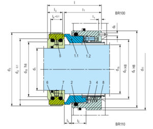
- EN 12756
- Direction of installation:
- From the impeller side: CS100
- From the bearing side: CS110
- Seal face: Silicon carbide (Q1, Q2)
- Seat: Silicon carbide (Q1, Q2)
- Sizes: dN = Upto 270 mm (Upto 10.625’’)
- Pressure: p1 *) = 16 bar (230 PSI)
- Temperature: t = -20 °C …+160 °C
(-4 °F …+320 °F) - Speed = 10 m/s (33 ft/s)
*) For operation under vacuum it is necessary
to arrange for quenching on the atmosphere
side.
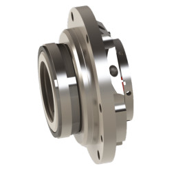
- Single and Dual seal configuration
- Balanced design
- Independent of direction of rotation
- Cartridge construction
- Stationary design with multiple springs
- Seat arrangement is designed behind
the impeller - Seat design is rotary
- Specially designed sleeve to protect the
springs from contamination - Variable designs available with guide sleeve for applications with or without
quench