Project Description
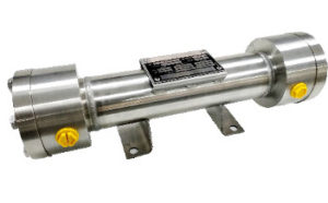
IFE- HEAT EXCHANGERS
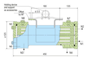
| Item No. | Description |
|---|---|
| N1 | Cooling water IN |
| N2 | Cooling water OUT |
| N3 | Process/barrier medium IN |
| N4 | Process/barrier medium OUT |
| N5 | Cooling circuit vent |
| N6 | Cooling water drain |
| N7/N8 | Process/barrier circuit vent |
- Cooling capacity up to 36 kW
- Installation can be done either in a
vertical or a horizontal position - For optimum and simple cleaning, the
heat exchanger can be dismantled - Compact design of tubular heat
exchanger with integrated guide
plates alongwith extremely efficient
cooling capacity - Designed for varied applications due
to construction in stainless steel
allows flush with a suitable solvent on
the process/barrier medium side
- Chemical industry
- Oil and gas industry
- Petrochemical industry
- Power plant technology
- Refining technology
- PED 2014/68/EU (Design and production in
accordance with EU Pressure Equipment
Directive)
ASME VIII, Div. 1 (Design, calculation and
production)
- Cleaning:
- Cooling water side: the area around the tubes can
be cleaned mechanically after the housing is
removed. - Process/barrier medium side: flush with a suitable
solvent.
- Circulation in accordance with API 682 /
ISO 21049: Plan 21, Plan 22, Plan 23,
Plan 41 - HED designed heat exchanger is
employed to cool process/barrier fluids in
seal supply systems. - Construction of the vessel is in a tubular
design with integrated guide plates, the
process/barrier medium is directed
through the shell of the HED and the
cooling medium through the tubes.


